3D visualisation of core technology | Micrometers to Megawatts
As part of an ongoing collaboration with multiphysical simulation and data scientists at resolvent both a 2D and 3D simulation tool has been built in conjunction with ongoing Reversible power-to-X technology for the dynamic production of eFuels – DynEfuel | EUDP project.
Resolvent explains the challenges and how they were able to solve these unique challenges. With permission, here is the full article.
Modelling of SOE Stack Technology for Renewable Hydrogen (resolvent.com)
There are several challenges ahead in order to achieve the European Hydrogen Strategy target of installing at least 80 GW of renewable hydrogen electrolysers by 2030 (40GW in Europe and 40 GW in Europe’s neighborhood with export to the EU [1]). Among other things, sustained research and innovation into breakthrough technologies is needed.
The EUDP-funded project “Dynamic Electrolyser for Offshore Production of Green Ammonia” (DynAmmonia, [2]) aimed at demonstrating the potential of the AC: DC operation technology of solid oxide electrolysis (SOE) stacks to increase the lifetime of the high-temperature electrolysis technology. As part of a research consortium of 7 key partners within the Power-to-X industry, we developed several models of SOE cells and stacks.
Developing numerical models for the transient simulation of SOE stacks can be quite challenging due to the multiple size scales (micrometers at the individual cell level to centimeters at the stack level) and time scales involved. The many different coupled physics also add to the overall complexity of such models, which typically results in computationally demanding models, both in terms of hardware and computation time.
In this blog post, we present a brief overview of the different models we developed using COMSOL®, the different methods we used to overcome the modelling challenges mentioned above, and how such models can provide valuable insights when designing dynamic electrolyser units.
2D single-cell model under AC: DC operating conditions
The system was initially simulated in 2D for a single cell consisting of an electrolyte membrane sandwiched between 2 porous gas diffusion electrodes and flow channels for air and fuel, as illustrated in Figure 1. This simplification of the geometry was necessary to achieve high running speed to simulate the time-dependent part of the AC: DC method. The system was modelled as a multi-physical system simulating the fluid flow, transport of concentrated species, electric current distribution, and heat transfer.

The AC: DC method consists in applying an asymmetric time-varying signal to the SOE stack in such a way that it alternates between electrolysis and fuel cell modes over a duty cycle that is typically of the order of a few tens of milliseconds. One of the advantages of running a SOE stack under AC:DC as opposed to the conventional DC operation is that the heat generated within the cells while operating in fuel cell mode helps balancing the heat absorbed while operating in electrolysis mode, thus reducing temperature variations within the stack. For a more in-depth explanation on AC:DC operation of SOE stacks, see Ref. [3]. Below is an example of the model running over two complete AC: DC duty cycles.
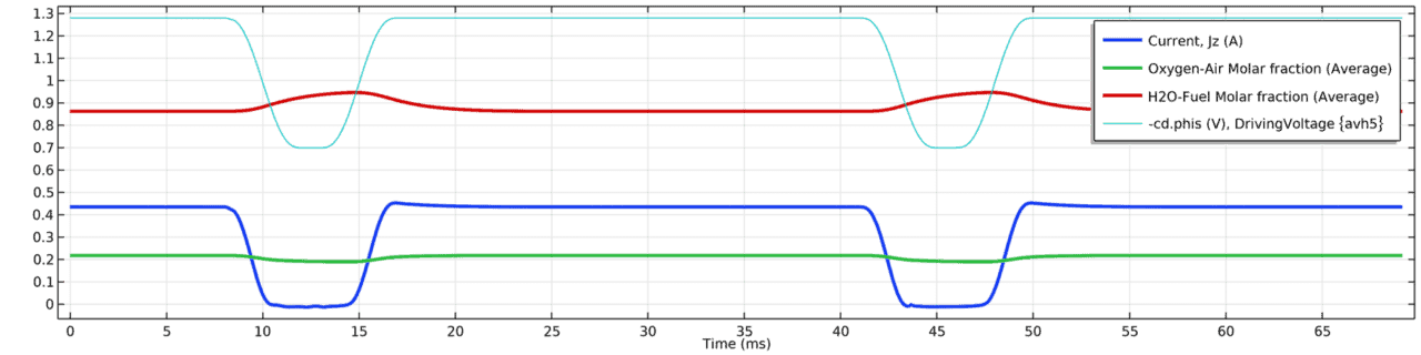
The AC:DC method has a time dependence that requires fine time stepping, which makes simulating it by conventional means unfeasible for any long timeframe, even with a simplified 2D geometry for a single cell. Therefore, we developed an effective algorithm that greatly reduces the number of time-steps that need to be calculated to simulate a given time period and reach steady state, thus significantly reducing computational time. This was implemented using Equation Based Modelling (PDE interface) and Model Methods within COMSOL®. As an example, the equivalent 1D model described in Ref. [3] takes about 10 seconds to simulate 1 AC:DC cycle or 2 weeks (computation time) to simulate 1h of AC:DC operation. In comparison, running our 2D single cell model on similar hardware combined with our effective algorithm takes about 3 minutes to simulate 1 AC:DC cycle, but only about 5 hours (computation time) to simulate 1h of AC:DC operation. Figure 3 shows a comparison of the transient temperature profile along a SOE cell under DC and AC:DC operation simulated using our effective algorithm.
To serve as design support tool, a simulation application was developed using the Application Builder within COMSOL®, see Figure 4 below. The application uses the 2D single cell model and allows the user to run inhouse simulations of the system under different system configurations and operating conditions. Within the application, the model can be calibrated by fitting simulation parameters to experimental data, for example, to reproduce characteristic current-voltage curves. Asides from displaying various physical quantities of interest (e.g., concentrations, velocities, temperature, and so on), the application can also help the user optimize operating conditions of the SOE stack by changing the duty cycle of the AC:DC method until reaching the desired temperature distribution within the stack. Minimizing temperature variations within a SOE stack is a key factor to maintain stack integrity for long term operations of the electrolyser and for dynamic operations (e.g., when using power from renewable sources like wind or solar).

2D SOE stack model under DC operating conditions
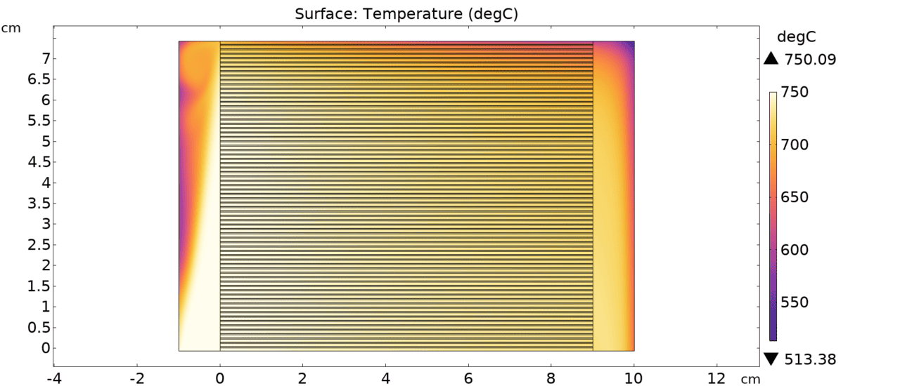
The 2D single cell model was extended to a 2D stack model consisting of 70 cells stacked together with inlet and outlet manifolds that distribute the air and fuel flows towards each individual cells. Scaling up from a single cell to a full stack unfortunately means that the model takes more time to simulate and is not a viable candidate for the AC:DC method, even with our effective algorithm. However, it can inform us about how specific quantities vary across the stack and help us investigate, for example, whether all cells receive the same amount of fuel, or if there are risks for the physical integrity of the stack caused by non-uniform temperature distribution within the stack. Figure 5 shows an example of temperature distribution in a SOE stack under DC operating conditions.
Hybrid 2D-3D stack model under AC:DC operating conditions
Some effects simply cannot be investigated in 2D, such as flow and temperature distributions in a SOE stack in the depth direction. In order to circumvent such limitations inherent to 2D models, some steps were taken to develop a 3D SOE stack that could run under AC:DC operating conditions. First, a homogenization process was used to avoid solving the relevant physics on a multiscale level as was the case in the 2D stack model, but instead solving only at the stack level. This trade-off between detailed solution of the physics at the smallest system scale and computational time was needed so that this new model could run under AC:DC operating conditions. An algorithm was then developed which couples our homogenized 3D stack model to the 2D single cell model and solves for the unknown variables iteratively, as depicted conceptually in Figure 6.
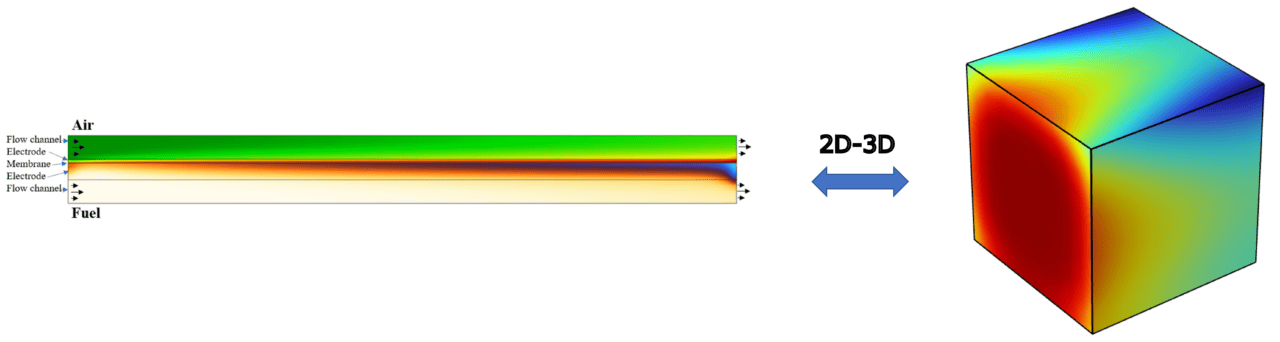
With our hybrid 2D-3D model, we were able to demonstrate that such an algorithm could potentially be used to significantly reduce computational time while still taking into account 3D effects in a SOE stack under AC:DC operating conditions. The hybrid 2D-3D stack model can directly build up on the two previously discussed models. It could, for example, take a flow distribution calculated from the 2D stack model as input to the 3D model within the iterative process, which would then account for flow variations across the stack that cannot be captured by the 2D single cell model alone.
Conclusion
With multi-scale and multi-physical models developed in COMSOL®, we provided insights on the design and optimal AC:DC operating conditions of solid oxide electrolysis stacks. The effective and 2D-3D iterative algorithms that we developed using “Model Methods” allowed us to extend the default capabilities of the software and address the challenges inherent to such complex multi-scale and multi-physical systems. The models that we developed within the DynAmmonia project will serve as a foundation for the up-scaling of the system in the upcoming second phase of the project under the EUDP funded project “Reversible Power-to-X technology for the dynamic production of eFuels” (DynEfuel).
References
[1] EUR-Lex – 52020DC0301 – EN – EUR-Lex (europa.eu)
[2] Dynamic Electrolyser for Offshore Production of Green Ammonia – DynAmmonia | EUDP